
While in RRC_IDLE the user equipment (UE) mobility is called cell reselection, on RRC_CONNECTED state is called handover. The main difference that exist between both procedures is that in cell reselection is the UE that controls the mobility through measurement on neighboring cells while in a handover is the network which takes control of the mobility using measurements reports from the UE.
Handover related events
Centuries ago, when people use their mobile phones to actually talk to another human being, GSM introduced an incredible concept: mobile assisted handoff (or MAHO). The idea is kind of the same of what happen in today LTE networks: the UE will send a periodic measurement in a form of reports to the eNodeB briefing about the signal strength and quality of its possible handover candidates. The eNB will passed to the UE what it has measure and how often in the RRC Connection Reconfiguration message. I’ll explain this procedure further in this post.
There is another thing that was adopted from past generations (3G) in LTE and it is the concept of events. As I mention before the measurement report is sent periodically, but is not sent all the time. For example the UE will send the measurement report containing inter-frequency and/or inter-RAT candidates only if the event A2 is triggered. The event A2 is related to the signal strength and/or quality of the serving cell; if the serving cell becomes worse than a certain absolute quantity, then the event A2 is triggered. As you can see the events are triggered when a set of conditions are met.
I’ve prepared this table to explain the different events related to handover that are defined in LTE and how each is triggered:
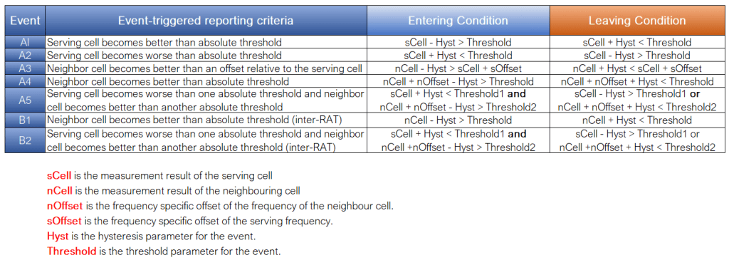
- Events A1 and A2 are related to inter-frequency and inter-RAT measurements. If event A2 is triggered, inter-frequency and/or inter-RAT measurements start. When event A1 is triggered, inter-frequency and/or inter-RAT measurements are stopped.
- The event A3 is about sending an inter-frequency or intra-frequency handover request.
- The events A4 and A5 triggers a request for an inter-frequency handover from the source eNodeB.
- The events B1 and B2 are to request an inter-RAT (LTE -> UMTS or LTE -> GSM or LTE -> CDMA2000) handover.
Measurement Gap
To perform inter-frequency and inter-RAT measurements the UE has to use measurement gaps. As the UE normally has one receiver it can only sintonize at one frequency at a given time. The measurement gap is characterized by two parameters: Tperiod which is the repetition period of the measurement gap and Tgap which is the gap width where the UE perform the measurement. Both parameters are given to the UE through the RRC Connection Reconfiguration message. In Huawei there is one parameter (GapPatternType) that allows you to choose between 2 different gap patterns or combinations of Tperiod and Tgap. I couldn’t find a similar parameter in Nokia, but if exist please let me know 🙂
RRC Connection Reconfiguration message
I got a Rohde & Schwarz Qualipoc handheld and it was if someone has lend me a PS5. If you have seen my other post you will notice that I use this tool to show layer 3 messages. So let me show you how an RRC reconfiguration message looks like:
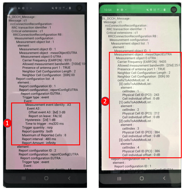
The RRC reconfiguration message has different formats. The one in the left, is passed to the UE in IDLE mode, while the one in the right is passed in RRC_CONNECTED mode. Please take in consideration that this message is very long, and I’m just showing a small part of it.
- <1> Here all the parameters related to each event are passed. In this case I highlight the Event A3 where you can see the offset (3dB) and hysteresis (1dB) that are common to all cells. The report interval (every 480 ms) and the report amount which establishes if there is a limit of reports to send or not. Another interesting parameter is the trigger quantity; we can decide if this event will be triggered by RSRP or RSRQ.
- <2> Now in RRC_CONNECTED the eNB passes to the UE which cells it has to measure. In this case I have highlighted the intra-cell list. After some parameters on how the measurement it must placed, the report is just a list of PCI and cell individual offset (this is a relation based offset) grouped in an index that the UE will use to identify it’s neighbors.
Just for fun I check another operator in the city and in RRC_IDLE the RRC reconfiguration message only passes information of UMTS carriers. When I place a call the UE did a CSFB to UMTS as this is the way they manage voice calls (no judging, but I’m writing this in march 2021). Anyway, each operator uses the strategy that best suits their needs.
UE Measurement Report
The measurement report sent from the UE to the eNB is a list of physical cell ID (PCI) and measurement quantities (could be RSRP or RSRP and RSRQ). The UE also reports the serving cell (PCell):
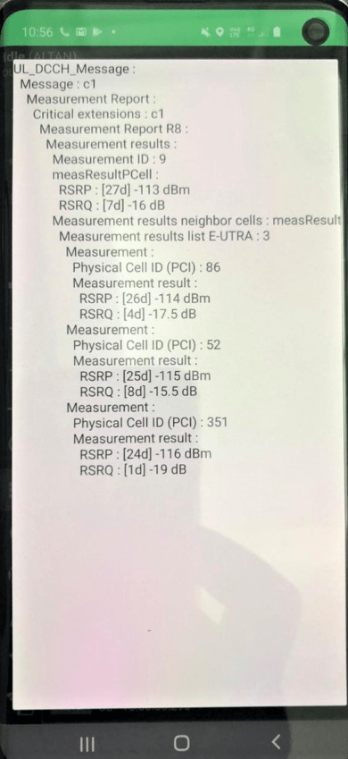
The UE perform 2 filters in the measurement before it sends it on the measurement report to the eNB. The first filtering is at the physical layer (L1) to tackle the impact of fast fading on the measurement results. The second filter is at the RRC layer (L3) and is intended to eliminate the impact of shadow fading and certain fast fading. One more thing: if you check the measurement report example there is the field measurement ID: 9. The object ID is linked to a certain report ID in a measurement ID. This is the way the eNB can differentiate one report from another.
Handover execution: X2 or S1?
I haven´t mentioned yet, but there are 3 main phases in the handover procedure:
- The first phase is the measurement phase, where the measurement is triggered. Here we have the measurement configuration (sent in the RRC reconfiguration message), the measurement itself (RSRP and / or RSRQ), the filtering process and the black cell list excluded (cells that are forbidden to participate in the handover for a certain relation). If the condition is met, then the UE sends the measurement report to the eNB.
- The second phase is the decision phase. Here the measurement report and the event triggered (if conditions are met) is evaluated. Priority takes place at this stage; frequency priority is part of the handover decision.
- The third and last phase is the handover execution. At this phase the admission control in the target eNB takes place. And also the signaling procedure execution.
Is at the third phase where it will be decided if the execution of the handover will be over the X2 interface or over the S1 interface.
In the handover execution phase the UE and the eNB exchanges signaling over the radio interface. During an inter eNB handover both source and target eNB exchange signaling through X2 interface or if this one is not available, through S1 interface. There is a big difference with UMTS in the handover execution and is that in LTE there is a hard handover; which means that there is only one radio link connected at a time. So to avoid data loss at the eNB during the handover the source eNB will still handling the data connection at the target eNB through X2 until the handover is completed. This procedure is call data forwarding.
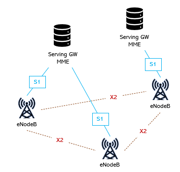
So if X2 interface is available the following procedure will take place:
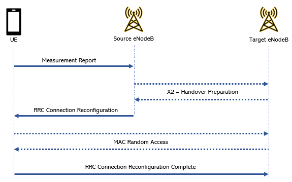
In my flashy picture there are some things I want to highlight that are very important :
1- Where is the MME or the SGW? If you noticed only the serving and the target eNodesB are controlling the handover. The target eNB decides if it has room enough (which is called admission control) for the entire connection or only for some RABs or no space at all to admit a handover. This negotiation is carried between serving and target eNBs with no participation of the MME whatsoever.
2- The random access that takes place at the handover might be contention free, that means that the target eNB might use a dedicate set of preambles for handover. I say “might be” as this is not mandatory. If you analyze SIB-2 might found that some operators do not have reserved preambles.
Conclusion:
My first post was a tiny part of this one. And although I know it was not perfect I decided to publish it anyway. Now I have rewrite this post and I have splitted it in two: this one with the theory and concept part, and another with handover optimization. I can sleep better now knowing is in the way I was aiming at the beginning. The other part of the post is related to practical cases of handover optimization. I hope you enjoy it!
Cheers!
Diego Goncalves Kovadloff
References:
LTE – The UMTS Long Term Evolution: From Theory to Practice Stefania Sesia, Issam Toufik and Matthew Baker, 2009 John Wiley & Sons
