

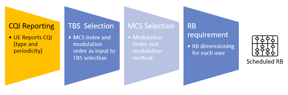
All connected user equipments (UEs) have requirements of resources. And although we all want to experiment the fastest available throughput the eNodeB has to offer, we can’t always get what we want (The Rolling Stones, 1969). The eNodeb has the difficult task to assign resources based on the amount of users, their equipment capabilities and the radio environment conditions each UE is dealing with. In this post I’ll dig into CQI reporting which is a very important part of the downlink data scheduling process.
Link Adaptation in LTE
Link adaptation techniques are not something new. On the second generation of data services over GSM called EDGE, the multi coding scheme (MCS) concept was introduced. MCS allows to select one of the nine available coding schemes for each chunk of data to be transmitted to each user depending on the radio conditions of the connection. The system checks on the bit error to estimate the error protection to use in exchange of data throughput. On the lowest MCS-1 a highest error protection was provided with GMSK modulation on expense of a lowest throughput per slot (8.8 kbps). On the other hand if the connection does require minimum error protection MSC-9 was selected with 8PSK modulation where up to 59.2 kbps of throughput per data slot was provided.
On LTE, similar to HSDPA (High Speed Downlink Packet Access), there is a dynamic adjustment of the modulation scheme and channel coding rate based on predictions of the channel conditions. This is done by means of the CQI (channel quality indicator) sent by the UE to the eNB in the uplink. The CQI in LTE (as in HSDPA) is not a direct indication of the SINR/RSRQ , but is based on measurements of the downlink reference signals and also takes into consideration the characteristics of the UE’s receiver.
CQI Reporting
As it was mentioned before CQI not only takes into consideration the radio channel quality, but also the characteristics of the UE receiver. This means that an UE that has better signal processing algorithms and more a robust interference cancellation techniques will report a better CQI. The 3GPP has defined that the CQI reported by the UE grants that a single PDSCH transport block with a combination of modulation scheme and transport block size (according to that CQI) that received by the UE will not surpass a 10% transport block error probability.
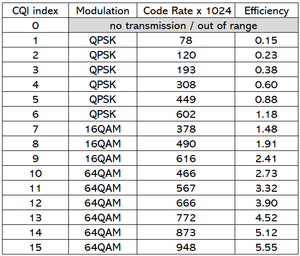
Note that this table is valid up to a modulation scheme of 64 QAM. But on release 12 it is established the support for 256 QAM in downlink, so the table for this release looks a little different, still the concept remains the same.
The 3GPP 36.213 defines the CQI as a 4-bit coded parameter, with values that stretches from 0 – 15. A low CQI value means that a more robust modulation is required and the code rate will be low, while a higher CQI value indicates that higher code rate can be supported by the channel. The table above shows the CQI value mapped in MCS and coding efficiency.
In situations where there is no valid CQI available or the CQI available is too old, Nokia offers the possibility to set a default CQI by means of parameters dlamcCqiDef. In Huawei there is a timer for using a static CQI during the handover phase. During the time the timer is active a static CQI is used preventing big variations of throughput. This is done through parameter CellDlschAlgo.HoStaticMcsTimer.
CQI reporting Types and Formats
The way the UE reports the CQI can be periodic or aperiodic. Periodic CQI reporting is delivered in the PUCCH (Physical uplink control channel). The reporting interval is determined by defining a number of subbands comprised by a number of Physical resource blocks (PRBs). On the other hand aperiodic CQI is delivered in PUSCH (Physical uplink shared channel). The type of CQI report is configured by the eNodeB by RRC signalling.
There are also variations on the CQI reporting type. The UE may report the CQI value for the whole system bandwidth in what is called Wideband Feedback. Or the UE additional to the wideband feedback it can also report a CQI value for specific sub-bands defined by the eNB (eNodeB-configured sub-band feedback) or by the UE (UE-selected sub-band feedback). Note that only wide band feedback is supported in the periodic CQI report.
One last thing about CQI reporting is that in the case of multiple transmit antennas at the eNodeB (MIMO), CQI value(s) may be reported for a second codeword.
CQI Adjustment
The eNB does another adjustment of the CQI reported by the UE based on the UEs HARQ ACK/NACK feedback. The CQI value is decreased is a NACK is received and is increased if an ACK is received instead.
CQI in the field
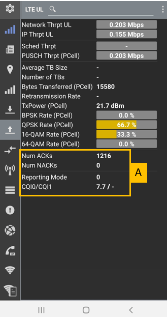
The screenshot above is an example of how the CQI report look like. If you check the highlighted section “A” you will notice that ACKs and NACKs are counted as they are part of the CQI adjustment. The Reporting Mode refers to the CQI aperiodic reporting mode. In this case 0 means that aperiodic report is not used. And finally the CQI reported by the UE. In the example, you can guess that the channel quality is far from ideal (I have to move to another location to do next tests)
Cheers!
Diego Goncalves Kovadloff
References
LTE – The UMTS Long Term Evolution: From Theory to Practice Stefania Sesia, Issam Toufik and Matthew Baker, 2009 John Wiley & Sons
Evolved Universal Terrestrial Radio Access (E-UTRA); Physical layer procedures (3GPP TS 36.213 version 10.1.0 Release 10) https://www.etsi.org/deliver/etsi_ts/136200_136299/136213/10.01.00_60/ts_136213v100100p.pdf
