

Happens that not long time ago I was working on an LTE network that suddenly begun to present paging discard in one tracking area (don’t judge me… I have a job because of incidents like this…). After looking at the issue I found out that the tracking area was not correctly dimensioned so the amount of paging messages were so high that the system simply cannot respond to all of them. This lead to a tracking area dimensioning analysis and the corresponding Tracking Area split to solve the problem. So if you face something similar in your network or you just want to know more about how a tracking area should be dimensioned, stick with me.
Tracking Areas
If you have some 3G background, you should be very familiar with a similar concept: Routing Areas. If you are coming from the past (like myself) or if you are new in LTE, it might be useful to dig into this concept. The tracking area is just a group or cluster of eNodeB that shares the same tracking code. Knowing in which Tracking Area (TA) the UE is moving provides a way to establish the location of the UE in idle mode (a procedure called location management). Also the MME provides the UE with a Tracking Area list, which is a list of TA where the UE registration is valid. The idea behind this is that first, the MME will page the UE only in a subset of Tracking Areas, and second the UE won’t necessary need to update the MME on changes of tracking area if is still on the same TA List. The illustration below explains this procedure:
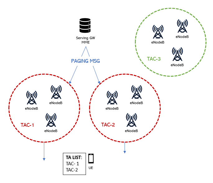
The MME sends to the UE the TA List during the TA Update procedure. Then the UE will update periodically the MME of it’s current TA and also when it enters a TA not listed in the TA list. This avoids Ping-Pong between TA borders within a certain TA list.
Tracking Area Registration
The eNodeB broadcast the tracking area code (TAC) through SIB1. Then the UE inform the EPC (Evolved Packet Core) in which Tracking Area (TA) it is located. It does this by a procedure called TA registration. This procedure takes place when the UE attach/detach or when it does a TA update (when changes from a cell with one TA to another cell with a different TA not listed in the current TA List). Notice that in order to access the network the UE has to perform successfully the TA registration procedure. After this the UE will be assigned an IP address so then it can share it’s MEI (mobile equipment identity) with the MME for authentication purposes.
Tracking Area Size
The number of eNodeB within a tracking area determine the tracking area size. If the amount of eNB is small the location of the UE will be more accurate, but also the number of tracking area updates will increase. This can impact the paging success rate as the UE cannot respond to a page during TA update. On the other hand, a tracking area containing too many eNB will increase the number of paging messages on the tracking area, and also the signaling load. If this is taken to the extreme, like in my example, paging discard may occur.
In order to calculate the correct number of eNB per Tracking area there are some things to consider, for example how many Paging messages the eNodeB can handle per second. This refers to the ability to process paging messages and to receive paging messages in each paging cycle. The other part to consider is how many paging messages the MME can handle per second.
Paging Procedure
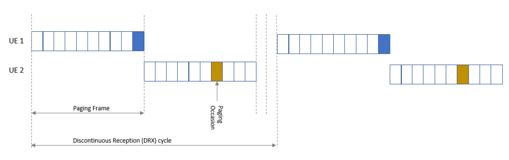
Paging is the process in which an idle UE is notified about an incoming connection. The idle UE has to monitor a paging occasion within a paging frame to check if there is an incoming paging message. The frequency the UE monitors the paging occasion is governed by the Discontinuous Reception (DRX) cycle setting. In Ericsson networks DRX is set with parameter defaultPagingCycle and in Nokia with parameter defPagCyc. Take note that the more often the UE has to monitor the paging occasions the more battery will be consumed by the UE.
The amount of paging occasions per radio frame is configurable by parameter in Nokia pagingNB and in Ericsson Nb. This parameter broadly set the eNodeB paging capacity, and is expressed as a fraction or a multiple of the default paging cycle (or DRX). So here we have two different scenarios:
- If the value of paging occasions is equal or larger than the default paging cycle, then all radio frames may be used for paging and the number of paging occasions per paging frame is defined by Nb/T (where Nb is the number of paging occasions and T is the default paging cycle).
- If the value of paging occasions is less than the default paging cycle, then there is a fraction of all radio frames (Nb/T) that may be used for paging and the number of paging occasions per paging frame is only one (like the example on the figure above).
As mentioned before, Nb will determine the paging capacity of the RBS. As the paging messages are delivered to the UE through the Physical Downlink Control Channel (PDCCH) and the Physical Downlink Shared Channel (PDSCH), then the value of NB can play an important role on the PDCCH load. Lowering the value of Nb will ease load on PDCCH at the risk of paging messages that cannot be responded on the first paging frame.
SGSN-MME capacity
MME capacity must be taken into consideration while dimensioning tracking areas. And (spoiler alert!) is usually the limiting factor when calculating the amount of RBS per tracking area. SGSN-MME paging capacity depends on the number of SCTP/S1 boards in the SGSN-MME and the hardware type. The capacity of the SCTP/S1 boards will be given in pages per second. The capacity of the SGSN-MME then will be the amount of SCTP/S1 boards times the capacity of a single board.
eNodeB paging Capacity
Here the capacity of the RBS is defined by several settings. The amount of paging records being transmitted per paging occasion is limited. This limitation is based on the value of Nb and the blocking probability allowed in your network for paging messages. Let me explain this relationship:
The paging records allows a specific number of pages per paging occasion with a certain blocking. There are tables that can gives you the number of paging occasions if let say you aim for a 2% of blocking. Then you can multiply the number of paging occasions you have by Nb/T (where Nb is the number of paging occasions and T is the default paging cycle) to get the number of paging’s per second that the RBS can support.
Other things that can affect the RBS or MME capacity
Inactivity timer tuning can help ease resources load in congested cells but it also has an impact on signaling towards the MME. Releasing the RRC connection sooner will impact the paging load. I have find that some people use this timer to mask retainability issues (but that’s another story). So if you are thinking in something like that, please consider the impact in Paging.
Lastly I want to let you know of my latest post on how to manage TAC/LAC in QGIS. If you are new to QGIS and you need to create tracking areas or check inconsistencies, this post will help you do the job.
Cheers!
Diego Goncalves Kovadloff

Great summary! TACs can cause so many headaches.
LikeLike