Dual Connectivity was born on 3GPP Release 12 as a way to increase coverage and/or UE data rate (throughput) on LTE networks. On DC the UE can communicate with two different eNB and each eNB communicates with each other by the X2 interface. Still there is some sort of independence between the eNB’s as each one use uses it’s own scheduler. The RRC signaling will be conducted through the so call Master eNB, which normally will be a low frequency and high coverage cell, and the additional throughput will come from the Secondary eNB which can be a small cell on the upper frequency band that can support higher data rates. Notice that the UE can be in carrier aggregation with the Master eNB or the Secondary eNB or both (this one can have more than one SCells, but all in DL).

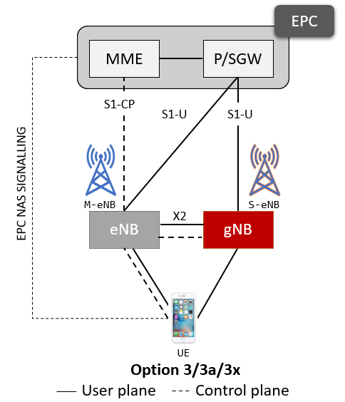
Moving forward to release 15 and the appearance of 5G-NR, the Dual Connectivity feature plays a crucial part on the initial 5G deployment. The initial 5G deployment I’m referring to is NSA (Non-Stand Alone) deployment, also called version 3/3a/3x, which requires an LTE eNB acting as a Master Node and the gNB as a Secondary Node.
Differences between Option 3/3a and 3x
All the different versions of the option 3 uses a LTE eNB as master node and the gNB as secondary node. In idle mode the UE will carry on all the idle mode tasks through the LTE node. These tasks are exactly the same as in LTE which consisted in:
- PLMN (Public Land Mobile Network) Selection
- Cell selection and cell reselection
- Obtaining System Information through reading it from the SIB (System Information Blocks)
- Location management which includes Tracking Area update and Paging
All the control plane goes through the LTE node, so in Idle Mode, there are no differences with the legacy LTE architecture. But things certainly are quite different in connected mode. Option 3 offers 3 different alternatives based on the same architecture. The difference between them is where the data is aggregated and who takes that decision; the eNB (Master Cell Group) or the gNB (Secondary Cell Group)
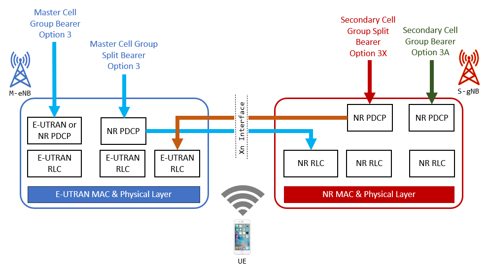
The Master eNB (LTE eNB) will handle all signaling and control. On the data flow part appears the different alternatives of the Option 3:
- On Option 3: Although the data route can be through the MeNB or the SgNB is the Master eNB which will decide which route data will take.
- On Option 3X: Also the data route can be through the MeNB or the SgNB but in this case is the Secondary gNB that will decide which route data will take. Is important to notice that the vast majority of NSA deployments choose Option 3X.
- On Option 3A: The data route is solely through the Secondary gNB
I have to mention that Option 7 (7/7a/7x) is also is a NSA alternative that is quite similar to option 3, but requires to have a 5G core network. I’ll not dig into this option in this post, but if you want to have a brief introduction to the different deployment options, you can visit my previous post “5G Deployment Options“.
Bearer Transitions
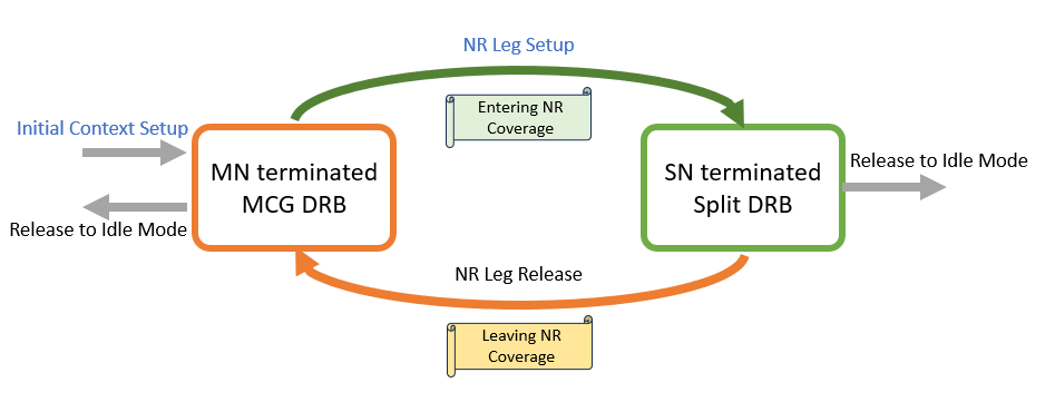
The initial context setup start at the LTE eNB, which in this case we will called it the Master Node (MN). The context is set up as MN as terminated Master Cell Group (MCG) Data Radio Bearer (DRB). At this point the user plane is routed solely on the LTE node. If in the MN coverage exist an NR that can act as a secondary node (SN), then a NR leg in dual connectivity is set up. This bearer is configured as a secondary node terminated split DRB. This will triggered a change in the PDCP version and change in the security key.
If the UE abandoned the NR coverage, then the NR leg must be released. The bearer that was setup before has to change its type MN terminated MCG DRB. Again PDCP version and security key will change back. This procedure not only can be triggered if NR is coverage is abandoned. Other reasons to start this procedure include NR Radio Link Failure (RLF), NR cell lock or even LTE cell handover.
Once the UE goes back to Idle mode, the eNB will release the UE and then will release any resources for the Split DRB in the eNB as well.
Initial Context Setup in Detail
As mentioned above at the initial context setup the bearers are setup as a MN terminated MCG DRB (or Master Node terminated Master Cell Group Data Radio Bearer). The 5G NR-DC capabilities are fetched from the UE if not received from the Core Network. In addition to this, a B1 measurement might be started (but this is optional). Adding a new NR leg, implies that the original radio data bearer is reconfigured to a split radio bearer. The addition of a new NR leg can be the result of B1 measurement report (the so called measurement based setup) or after the Initial Context Setup is completed (Configuration based setup)
To be continued…
Cheers!
Diego Goncalves Kovadloff
References:
3GPP, “3rd Generation Partnership Project; Technical Specification Group System Architecture; System architecture for the 5G System (5GS) (Release 15),” 23.501, v15.8.0, December 2019.
3GPP, “3rd Generation Partnership Project; Technical Specification Group System Architecture; Procedures for the 5G System (5GS) (Release 15),” 23.502, v15.8.0, December 2019.
3GPP, “3rd Generation Partnership Project; Technical Specification Group Radio Access Network; NG-RAN; Architecture description,” 38.401, v15.7.0, September 2019.