
The user equipment must identify which cell is connecting to, in the early phase of network access. In AMPS (IS-553) it was used a supervisory audio tone (or SAT) to identify one cell from another and also to estimate channel quality. On TDMA (IS-136) it was the digital verification color code (DVCC), on GSM mounted over the BCCH it was the BSIC (Base station identity code), in UMTS it was the primary scrambling code (PSC) and in LTE it is the Physical Layer Cell Identity or PCI the one that takes care of the cell identification. Cell identification is important for access and handover and in LTE the cell identification is calculated from the synchronization signals.
UE synchronization in LTE
The UE synchronize to the eNB reading the primary and secondary synchronization signals (PSS and SSS respectively). By reading both signals the UE achieves time and frequency synchronization (frame, subframe, slot and symbol synchronization in the time domain; and it identifies the center of the channel bandwidth in the frequency domain) and calculates the Physical Layer Cell Identity or PCI.
The Physical Layer Cell Identity (PCI) is used to identify a cell within a network and there are only 504 possible physical layer cell identities. So, chances are that each of the 504 PCIs are used more than one time in the network.
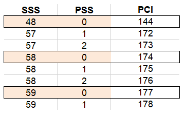
The Physical Layer Cell identity is composed of NID1 extracted from the SSS and the NID2 extracted from the PSS. The formula to calculate the PCI is the following:
PCI = (3 x NID1) + NID2
NID1: Physical Layer Cell Identity group. Defines SSS sequence in a range that goes from 0 to 167.
NID2: Identity within the group. Defines PSS sequence in a range that goes from 0 to 2.
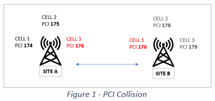
There are two main things to avoid in PCI planning: the PCI collision and the PCI confusion. The first one happened when there are two neighbor cells with the same PCI, and the last one is when there is a cell with two neighbors with the same PCI (mentioned in my previous blog). Here are examples of the two kind:

But if you have check in “the internet” there are other rules that are desired to follow when planning PCI allocation. These rules say that is desired to avoid neighbors with the same MOD3, MOD 6 and MOD30 PCI. So, what is this means and how is this important? To explain it we have to take a look of the resource elements (RE) and how the reference signals (RS) are mapped.
DL Reference signals in LTE
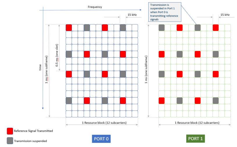
A resource block are the 12 OFDM sub-carriers during a 0.5 s slot. The smallest unit that can be allocated by the scheduler is two consecutive resources blocks (12 OFDM sub-carriers during 1 ms, or 1 TTI)
In the frequency direction there is only 1 RS every 6 sub-carriers, but if more than one antenna is used, each antenna port utilizes a different RS pattern. Intra-cell interference is minimized between the multiple transmit antenna ports when one RS is transmitting in a particular slot and nothing is transmitted in the other port in the same slot.

MOD3, MOD 6 and DL Reference Signals
The PSS and SSS determines the position of the RS on the resource block. The diamond shape is maintained, but the position of the RS are moved in the frequency direction by one sub-carrier on each PCI increment. So PCI 175 displayed the RS 1 sub-carrier to the right (according to my picture above) than the PCI 174 and so on.
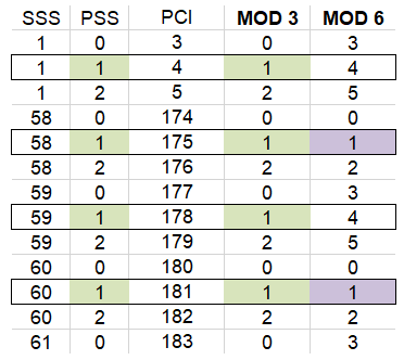
So you might be figuring out what these MOD3 and MOD6 means. In a one port scheme the pattern is repeated each 6 PCI increment, and on the two port scheme it is repeated every 3 PCI increment. To avoid RS interference, MOD3 and MOD6 PCI in neighboring cells should be avoided.
What happen in the up-link?
LTE Single-Carrier Frequency Division Multiple Access (SCFDMA) uplink uses Reference Signals (RSs) for data demodulation and channel sounding. Not going to deep in the theory, what we need to know is that as in down-link there is a pattern that is repeated each 30 PCI. This happened because in up-link reference signals in LTE are based on Zadoff–Chu sequences and there are 30 special RS sequences defined. So this is the reason that MOD30 PCI should be avoided in neighbor cells.
Conclusions
Let me put an example on the table: imagine you have a new sector added on a 3 cell eNB. So if MOD 3 was avoided, now there is no chances that this could be true. What we normally do is on a 3 cell select an SSS and rotate the PSS among the cells (e.g. 0,1,2 or 181, 182,183). So how you select a PCI for the sectorization that complies with MOD3 rule? there is no way!
So in real life, if you can avoid PCI collision and PCI confusion, you deserve a medal. These two scenarios are the ones with more impact on your accessibility and drop (due HO failure).
As you can imagine, there is a lot more of theory than what I have presented here. If you feel hungry for more, please check my references. Also if you want to check how PCI in LTE differs from 5G, check out my post 5G Synchronization Procedure.
Cheers!
Diego Goncalves Kovadloff
References:
3GPP TS 36.211. “Evolved Universal Terrestrial Radio Access (E-UTRA); Physical Channels and Modulation.” 3rd Generation Partnership Project; Technical Specification Group Radio Access Network. URL: https://www.3gpp.org.
Goff Hill (2007). The cable and telecommunications professional reference, PSTN, IP and Cellular Networks and Mathematical Techniques. Elsevier Inc.
LTE – The UMTS Long Term Evolution: From Theory to Practice Stefania Sesia, Issam Toufik and Matthew Baker. 2009 John Wiley & Sons.
Amazing Finding:
Looking for information about AMPS and TDMA I just came across this page. I know some friends that will be very emotional with this content. Enjoy!
http://rfmw.em.keysight.com/rfcomms/refdocs/is136/is136_gen_bse_tch.html

Very simple and useful way to understand how important is the correct PCI management.
LikeLike
Thanks for your feedback Ismael!!!
LikeLike
Great
LikeLike
Thanks very much for the useful and brief explanation
LikeLike