Throughput is a basic KPI on any LTE network. Is one of the three major KPI, along with and latency and packet loss when we measured what it’s called “the integrity” network. This post is to address common issues that affects downlink throughput and also to dig into possible solutions.
This approach can also be extended to any other KPI you want to improve. The first step is to identify the counters that are part of the indicator, and analyze how they are stepped. Let’s take a look of how throughput is commonly measured:

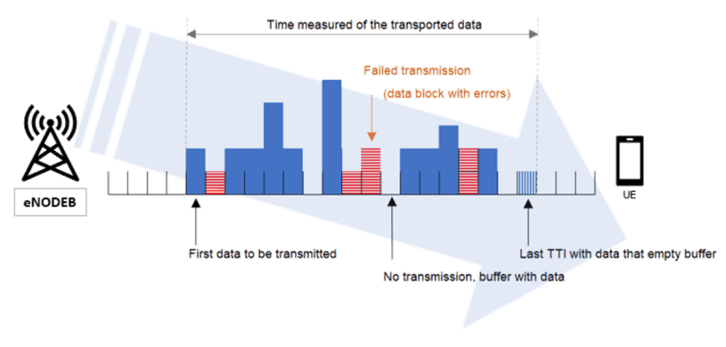
The throughput measurement starts with the first data to be transmitted, that is the first block to be sent into the air interface (uU interface) and ends with the last TTI with data that will actually empty the buffer. Noticed that there is not a continuous flow of data taken into the measurement; there are transmission gaps where no data is sent and also failed transmission that will need to be retransmitted. The DRB (Data Radio bearer) traffic volume carried in acknowledge mode or unacknowledged mode RLC (radio link control) that is been transferred to the UE in the downlink direction is measured in the PDCP (Packet Data Convergence Protocol) SDU. In very generic terms we can say that the downlink throughput is the information sent to the UE in a period of time. We can model this statement into a formula like the one below:
DL Throughput = (DRB Data Transmitted – Last TTI data) / Time Elapsed
where DRB stands for Data Radio Bearer
Last TTI with data is an indicator that the data transmitted has finished, and does not add to the user throughput so is normally removed from the equation. Both Ericsson and Huawei user throughput formula taken into consideration this. I have added Huawei and Ericsson DL user throughput formula at the end of this post, just as reference as they might not been updated. Counter name may vary from release to release.
Another thing to consider is that throughput can be discriminated by QCI. This is something necessary when you have VoLTE. But overall, the formula does not change, and it is visible that there are 2 ways of improving the measurement: 1- Increase the DRB data transmitted and 2- Reducing the time of the transmission. We can group causes under these two categories:
Increasing DRB data
1- Scheduler Fairness:
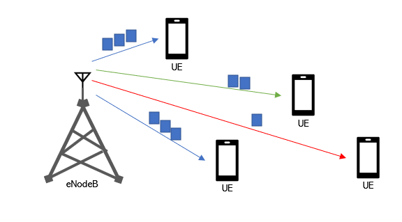
The scheduler is the main responsible of selecting how much data blocks will be assigned to an UE. It decides how data blocks are distributed utilizing as inputs the available PRBs on the cell, the available downlink power on the cell, the available PDCCH resources, the amount of data to transmit, and the estimation of the radio conditions (channel quality) of the UE. Then it applies an specific algorithm and a resource allocation strategy to assign data blocks to the UEs.
Each vendor has other it’s own set of scheduling algorithms (besides round robin) that applies more or less fairness on how data is scheduled. The fairness or not of the scheduler will impact not only how an UE in a low quality area is treated, but also it will shape the overall cell throughput. Speaking of low quality area, you might want to look up to pZeroNominalPusch and pZeroNominalPucch parameters as having them too high will higher signal power that might increase interference at cell edge. Lowering both too much can also lead to the opposite.
In terms of allocation strategy frequency selective algorithms works very well in noise limited networks. Ericsson has a feature called “frequency selective scheduling” (both UL, DL and after 2020 Q3 Evolved uplink frequency scheduling) that works great in this sense.
2- Radio Conditions:
The radio conditions are the reason that you see failed transmission blocks (red blocks) on the picture above. Spotting low SINR and/or bad RSRP areas can be done in several ways; through statistical counters, by means of a drive test equipment or through a more sophisticated drive-less toll like Viavi Nitro Geo.
Overall the radio conditions can be measured through the CQI (Channel Quality Indicator). To get reasonable good throughput a CQI better than 10 is needed.
Another thing to reviewed is the uplink RSSI. High values (higher than -104 dBm) could impact throughput, but in this case UL throughput.
3- Capacity Exhaustion:
Actually this is the first thing to check in a case of low throughput: the amount of RRC connected users and the available PRBs. In case you face this issue the remaining things to do are traffic balancing and adding more infrastructure or bandwidth (you might want to check my previous post Spectrum Refarming). Other things that can help ease PRB utilization (but needs other checks before implementing) are reducing the tInactivityTimer (it will also increase signalling) and the reduction of control channels resources (it might impact PDCCH utilization).
4- Modulation Scheme:
256-QAM DL can offer 45 Mbps peak rate higher than 64-QAM in 20 MHz carrier and 2-layer MIMO. Improving the utilization of 256-QAM modulation scheme is not easy. First of all is heavily dependant on the radio conditions. Secondly it requires that the UE support this modulation (several places in latin america faces shortage in this item). The other thing that it might prevent of using such modulation scheme is the available power headroom in the TRXs.
Reducing transmission time
1- Carrier Aggregation settings:
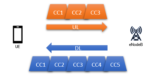
Carrier Aggregation allows to add more carriers (component carriers) to increase bandwidth. It can be added up to 5 component carriers of 20 MHz in the downlink for a total bandwidth of 100 MHz. These component carriers can be of different bandwidth and allocated in the same frequency, contiguous or separated or even in different frequencies, which gives flexibility to implement and efficiency of use.
Other things to consider
MIMO settings: Spectral efficiency is driven by MIMO settings and the amount of TX/RX antenna in array. This is something to take into consideration on a planning stage, but in case of low throughput features installed regarding this item should be reviewed.
Packet Loss: Transmission or Core related issues that can be translated into packet loss will impact definitely user throughput. A packet loss above 1% is noticeable from the UE perspective (and is a killer for VoLTE). I have found issues like this one when transmission comes from a chain of MW. TWAMP statistics can help you find this kind of issues.
UE category: This impact not only the usability of higher order modulations like 256-QAM, but also MIMO transmission modes can be limited, and the amount of component carriers (on carrier aggregation) that the UE support.
Handover attempts: To avoid data loss at the eNB during the handover the source eNB will still handling the data connection at the target eNB through X2 until the handover is completed. This procedure is call data forwarding. Still if you have too many handover back-and-forth (ping pong) this slight data interruption can cause a low throughput issue. If you want to dig more into this topic I have 2 post on handover that might be useful.
Lastly I have written a post on how to improve UL throughput hoping it will be of help to understand the challenges and propose some solutions to the issue.
Cheers!
Diego Goncalves Kovadloff
References:
Trinh Van Chien and Emil Björnson (2017). “Massive MIMO Communications” (PDF) part of “5G Mobile Communications”, Ed. Wei Xiang, Kan Zheng, Xuemin (Sherman) Shen
Specification #36.300

DL DRB Throughput Formula:
Huawei
User THP = L.Thrp.bits.DL – L.Thrp.bits.DL.LastTTI)/ L.Thrp.Time.DL.RmvLastTTI
Ericsson
User THP = [(pmPdcpVolDlDrb – pmPdcpVolDlDrbLastTTI)/(pmUeThpTimeDl/1000)]
Interesting Stuff:
I have found a list of things that can affect throughput in telecomhall.net that I mostly agreed. You can check that post in the following link: